PROFILM METER
Turn Your Phone into a Precision Light Meter for both Film & Plate Photography
ProFilm Meter turns your phone into a highly accurate light meter engineered for demanding analog workflows. Designed for both modern film and historical processes, it delivers precise exposure readings across materials with different spectral sensitivity modes including blue-sensitive, orthochromatic, and panchromatic. Advanced features such as two-point calibration, reciprocity failure correction, bellows compensation, and real-time colour temperature analysis ensure reliable results in any lighting condition.
Available on Android and IOS
The professional light meter built for film photographers. On your phone.
Precise. Trustworthy. Film-first.
Most light meter apps are built for digital photographers who think in stops and histograms. ProFilm Meter was built from the ground up for the way film photographers actually work — with reciprocity failure, spectral sensitivity, bellows compensation, and the ritual of getting the exposure right before you press the shutter.
Whether you're shooting 35mm on the street or a 4×5 sheet in the studio, ProFilm Meter gives you the accuracy and depth of a dedicated meter in the device you already carry.
Real metering. Real control.
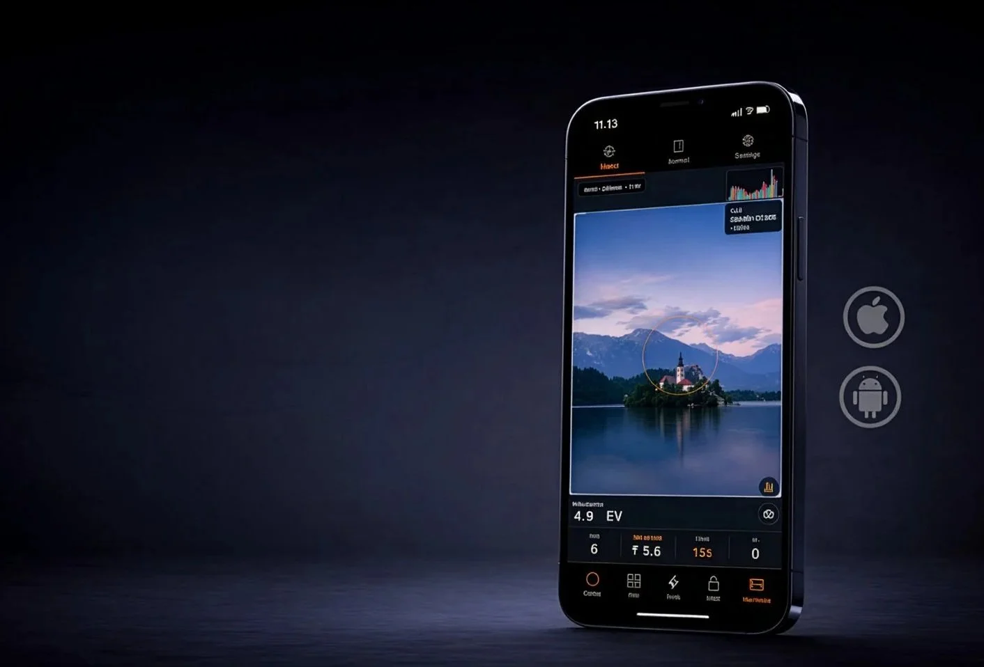
Four metering modes. Spot, center-weighted, average, and multi-point — take up to four readings and let the meter calculate the averaged EV automatically. Bracket without guessing.
Three priority modes. Aperture priority, shutter priority, or full manual. Lock your exposure and work the scene.
Flash metering. Trigger via optical flash sync, cable, or ambient light sensor. The meter captures peak luma, calculates your flash EV, and even suggests RA4 filter packs from the flash's color temperature. No separate flash meter required.
Live color temperature. See the scene's CCT in real time, so you know what you're printing into before you shoot.
Built around your film.
ProFilm Meter ships with a library of the most-used emulsions, and connects to a continuously updated remote database of film profiles you can pull in on demand. If your stock isn't there, add it yourself — with custom ISO (including fractional values), spectral sensitivity, and its own reciprocity curve.
Spectral sensitivity modes let you shift the meter's response to match how your film actually sees light: Panchromatic, Orthochromatic, Blue-sensitive, and Infrared.
Reciprocity is handled automatically. Every film profile carries its own Schwarzschild p-factor. Long exposures are corrected in real time so the time you set is the time that works.
Every tool you actually need.
Reciprocity Calculator — Corrects metered time to compensated time for any film in your library. Adjustable threshold per stock.
Depth of Field Calculator — Near and far focus limits, hyperfocal distance. Pick your format, focal length, and aperture.
Bellows Compensation — Enter focal length and extension distance, get the exact number of stops to add. Macro and large format ready.
IR Estimator — Estimates infrared offset for 720nm and 850nm filters from the current scene EV. No more bracketing blind.
Rolling Shutter Calculator — Know whether your shutter speed will cause banding artifacts before you fire.
Step Wedge Tool — For darkroom workers calibrating film development and printing processes.
Zebra Exposure Guide — Visual zone mapping that puts skin tones, shadows, and highlights into context for your scene.
Alternative Processes Meter — Exposure guidance for cyanotype, platinum-palladium, silver gelatin, and other non-standard processes.
RA4 Color Engine — CMY filter pack recommendations direct from the scene's color temperature. Walk into the darkroom with a starting point, not a guess.
Calibrated to your device. Your lens. Your workflow.
No two phone cameras are the same. ProFilm Meter includes a full two-point calibration system — calibrate to a dark reference and a bright reference to correct your specific sensor. Front and rear cameras are calibrated independently. Lens calibration accounts for field-of-view differences between your phone's optics and the lens on your camera.
The result is a meter you can actually trust.
Shoot and record.
Every exposure gets saved to your journal — ISO, aperture, shutter speed, EV, focal length, film stock, GPS location, date, and a cropped snapshot from the viewfinder at the moment you metered.
Share individual entries as a branded ProFilm Card — a photo with all your exposure data overlaid, ready to post or archive. Or export a full digital contact sheet across multiple entries.
Your gear. Your way.
Build out your kit in the app: custom lenses, custom aperture series (full, half, third, or two-third stops), and custom film formats down to the millimeter. Save your favorite camera, lens, and film combinations as Preferred Setups and switch between them in a single tap.
Environmental compensation runs automatically in the background — elevation and UV index adjust your readings based on GPS and local weather, so you're always metering for the conditions you're actually shooting in.
Available in eight languages.
English · Español · Français · Deutsch · Slovenčina · 日本語 · 中文
Metric and imperial. Your choice.
Instructions to build your own Camera to flash sync cable
Warning, if you mess this up you may destroy your phone. If you do it is on you
This is for using your phone to trigger your flash VIA a USBC to 3.5mm headphone jack. For my google pixel 9 using the Sine waveform and 500ms Burst Length, Flash Sensitivity at 1.08 with a flash duration that matches the flash in use this works well. On my Ipad pro with the same dongle a Square waveform works best. I have tested a bunch of different dongles and you get what you pay for as the cheap ones tend to be less reliable. In short you will have to play with it to figure out what settings work best with your hardware.
SIMPLE USB-POWERED FLASH TRIGGER
=================================
USB 5V POWER
------------
USB +5V
|
|
R3 680Ω
|
|
PC817 Pin 1 (LED +)
PC817 Pin 2 (LED -)
|
Collector
2N3904
|
Emitter
|
+-------------------- GND
|
USB Ground
|
+-------------------- Phone Sleeve
PHONE AUDIO INPUT
-----------------
Phone Tip
|
|
C1 10µF
(+ toward phone)
|
+------ R1 1kΩ ------ Base (2N3904)
|
R2
10kΩ
|
GND
OPTIONAL STABILITY CAPACITOR
----------------------------
Base (2N3904)
|
C2 1µF
|
GND
FLASH CONNECTION
----------------
PC817 Pin 4 -------- PC Sync Center
PC817 Pin 3 -------- PC Sync Shell
USB NOISE FILTER (recommended)
--------------------------------
+5V USB
|
100µF
|
GND
and also add:
+5V USB
|
0.1µF
|
GND
Important Notes
Electrolytic Capacitor Orientation
C1
Positive side → Phone
Negative side → transistor base network
100µF USB filter capacitor
Positive → +5V
Negative → GND
| Part | Value |
| ------------- | ----------------- |
| Q1 | 2N3904 or BC547 |
| Optocoupler | PC817 or PC817C |
| R1 | 1kΩ |
| R2 | 10kΩ |
| R3 | 680Ω |
| C1 | 10µF electrolytic |
| C2 (optional) | 1µF |
| Supply filter | 100µF + 0.1µF |